Panel Configuration
The Panels section in ElauPro allows you to define and configure the actuators needed for your KNX project. This is where you'll organize all the physical components that will be installed in your electrical distribution panels.
Panel Properties
To create a new panel:
- Navigate to the Panels section in the left menu.
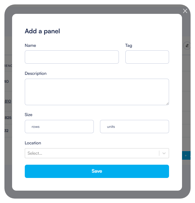
- Click the Add a panel button in the top-right corner.
- In the dialog that appears, complete the following information:
- Name: Enter a descriptive name for your panel (e.g., "Panel 1", "Main Panel", "Floor 1 Panel").
- Tag: Optional identifier that can be used for referencing.
- Description: Additional details about the panel's purpose or location.
- Location: Select the room where the panel will be installed.
Size Configuration
When creating a panel, you must define its physical dimensions:
- In the Size section of the panel creation dialog, enter:
- The width (number of horizontal units).
- The number of rows.
- The system uses these dimensions to calculate the available space for mounting modules.
- The total space is measured in "U" (units), which is the standard measurement for electrical panel components.
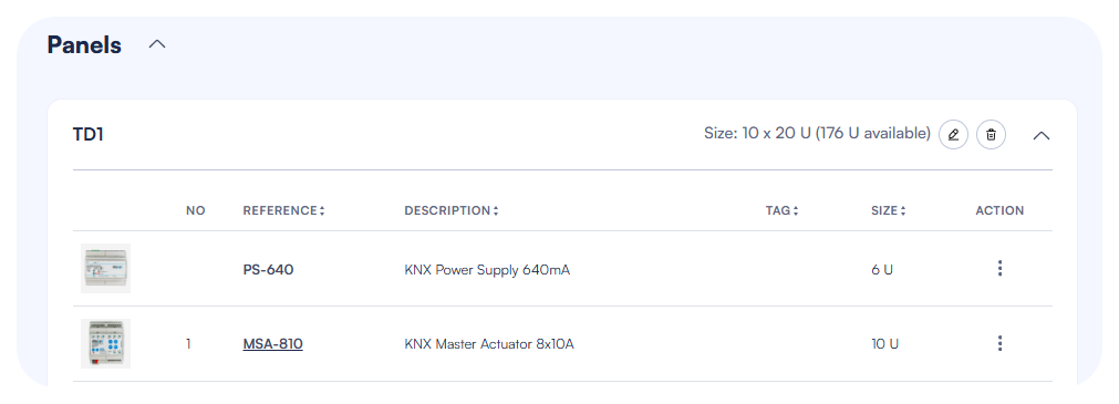
- After saving, the panel header will display the size information with the number of units on each row and total available units in the panel taking into account what is already used.
ElauPro automatically tracks the available space in your panel based on the modules you add:
- The panel header shows the total panel dimensions and remaining available units.
- Each module consumes a specific number of units (e.g., KNX power supply: 6U, HyperVisu Server: 4U).
- Adding extensions to a master actuator is automatically limited if the panel width is reached.
Adding Modules
Once your panel is created, you can add the necessary modules that will be installed in it. ElauPro supports various types of modules that are commonly used in KNX installations.
Power Supplies
Every KNX installation requires power supplies to provide electricity to the KNX bus and auxiliary components:
- With your panel open, click the Add Device button.
- Select from available power supply options:
- KNX Power Supply (e.g., PS-640): Provides power to the KNX bus (typically 640mA).
- Auxiliary Power Supply (e.g., PSA-30W): Provides additional power for components that require it (e.g., 24V DC).
- Each power supply will consume a specific number of units in your panel (shown in the Size column).
Note: The KNX standard recommends using power supplies that provide sufficient current for your installation. A typical 640mA power supply can support around 64 KNX devices.
HyperVisu Server
To enable visualization and control through the HyperVisu application, you need to add the HyperVisu server to your panel:
- Click Add Device in your panel.
- Select the HyperVisu Server (HVS-KNX) from the available modules.
- The server requires 4U of space in your panel.
- This server will be the central hub for connecting your KNX installation to the visualization interface and providing advanced automation features.
You will also need to add a KNX IP Interface (KNX-IP) to enable communication between the KNX bus and the HyperVisu Server.
Master Actuators
Master actuators are the core components that control your devices:
- Click Add Device to add a Master Actuator to your panel.
- Select the appropriate actuator type (e.g., MSA-810) based on your project needs.
- Each master actuator typically provides 8 channels (in this example, 8x10A relays) for controlling devices.
- After adding a master actuator, you can:
- View technical specifications
- Add extensions to increase channel capacity
- Edit channel configurations
- Link devices to specific channels
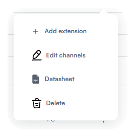
When you click on the action icon (three dots) next to a master actuator, a context menu appears with options to:
- Add extension
- Edit channels
- View datasheet
- Delete the module
Managing Project Channels
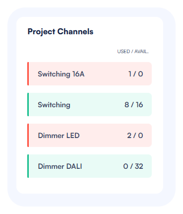
The right side of the Panels page displays a "Project Channels" section that shows:
- Required channel types based on your configured devices
- Used/Available channels (e.g., Switching: 1/8)
- Visual indicators (green when sufficient channels are available, red when more channels are needed)
Important: Monitor the "Project Channels" section to ensure you have enough channels of each type to support all your devices. If you need more channels, you can add extensions to your master actuators or add additional master actuators to your panel.
After configuring your panel with all necessary modules, you can proceed to the Output Configuration step, where you'll link your devices to specific actuator channels.
Output Configuration
The Output Configuration page is where you connect your defined devices to the physical actuator channels. This establishes the link between the logical devices in your project and the physical outputs that will control them.
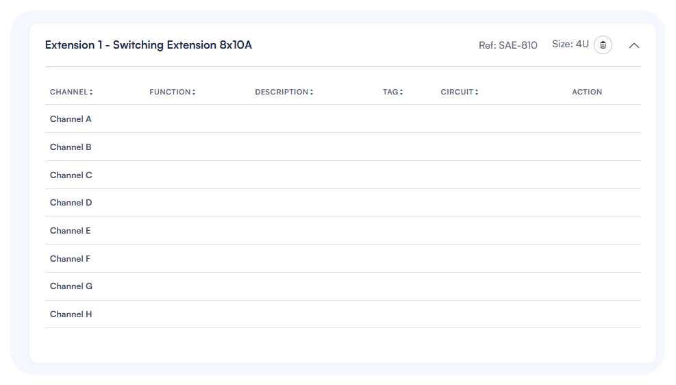
Adding Extensions
If your project requires more channels than are available on your master actuator, you can add extension modules:
- Click on a master actuator reference in your panel list to access the output configuration page.
- Click the Add Extension button at the top of the page.
- Select the appropriate extension type (e.g., "LEDs Extension 8x2A 12-30VDC" for LED dimming).
- The extension will appear below the master actuator with its own set of channels.
- Extension position can be rearranged by drag and drop.
Each extension has:
- A reference code (e.g., LAE-802)
- Size information (typically 2U for most extensions)
- Channel listing specific to the extension type
Note: Extensions must be physically connected to their master actuator when installed. The order in ElauPro should match the physical installation order.
Available Extension Types
ElauPro supports a wide range of extension modules to accommodate various device types in your KNX installation:
| Reference | Description | Number of channels | Size (U) |
|---|---|---|---|
| SAE-410 | Switching Extension 4x10A | 4 | 2 |
| SAE-810 | Switching Extension 8x10A | 8 | 4 |
| SAE-1210 | Switching Extension 12x10A | 12 | 4 |
| SAE-2410 | Switching Extension 24x10A | 24 | 6 |
| SAE-416 | Switching Extension 4x16A | 4 | 2 |
| SAE-816 | Switching Extension 8x16A | 8 | 4 |
| DOE-825 | Digital Outputs Extension 8x0,25A | 8 | 2 |
| HAE-805 | Heating Extension 8ch. 24/230V | 8 | 4 |
| LAE-802 | LEDs Extension 8x2A 12-30VDC | 8 | 2 |
| AAE-410 | Analog Extension 0-10V | 4 | 2 |
| DAE-225 | Dimming Extension 2x250W | 2 | 4 |
| DBE-32 | DALI Bus Extension 32 devices | 32 | 4 |
| DBE-48 | DALI Bus Extension 48 devices | 48 | 4 |
| DBE-64 | DALI Bus Extension 64 devices | 64 | 4 |
When selecting extensions, consider:
- Switching Extensions: For standard on/off control of lights, outlets, and other devices. Available with different current ratings (10A or 16A) and channel counts.
- Digital Output Extensions: For controlling devices requiring low current signals (12-30V DC).
- Heating Extensions: Specifically designed for controlling heating systems with 24V AC or 230V AC actuators.
- LED Extensions: Designed for LED lighting control with 12-24V DC power.
- Analog Extensions: For controlling devices that require 0-10V control signals (such as certain dimmers or HVAC equipment).
- Dimming Extensions: For traditional 230V AC dimming of resistive and inductive loads.
- DALI Bus Extensions: For integrating DALI lighting systems, with options to support different numbers of DALI devices.
Select the appropriate extension based on the device types in your project and their electrical requirements.
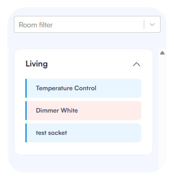
Linking Devices to Channels
To assign devices to actuator channels:
- On the Output Configuration page, you'll see:
- Left side: Actuator channels (Channel A through H for most master actuators)
- Right side: Available devices organized by room
- To link a device to a channel, drag the device from the right panel and drop it onto the desired channel.
- Once assigned, the device will:
- Appear in the Description column for that channel
- Display its tag in the Tag column
- Disappear from the available devices list on the right
- The Function column will show the channel type (e.g., "Switch On/Off 10A", "LED Dimmer")
If you need to change an assignment:
- Click the trash icon in the Action column to remove a device from a channel
- The device will reappear in the available devices list
- You can then reassign it to a different channel
Channel Tags and Descriptions
ElauPro automatically manages channel information when you link devices:
- Description: Shows the room name and device name (e.g., "Living room - Light 1")
- Tag: Displays the device tag (e.g., "L1" for a light)
- Function: Indicates the channel type (e.g., "Switch On/Off 10A")
These descriptions and tags will be used:
- In the ETS export for KNX programming
- In reports for installation documentation
For better organization, the devices on the right panel are color-coded based on their channel type requirements, making it easier to match devices with compatible channels.
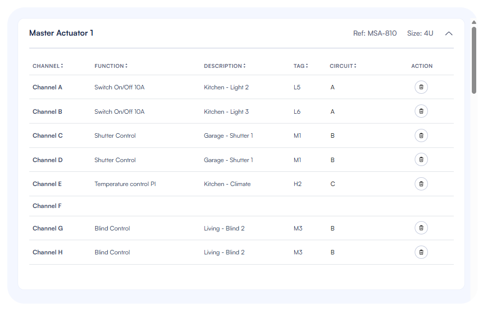
Circuit Numbering
For electrical documentation purposes, you can add circuit numbering to your channels:
- Each channel has a Circuit column where you can add the electrical circuit number.
- This helps electricians identify which circuit breaker corresponds to each channel.
- To add or edit a circuit number:
- Click in the Circuit field for the channel
- Enter the circuit number (typically corresponding to the breaker number in the distribution board)
- Press Enter to save
Circuit numbering is especially useful for:
- Installation documentation
- Maintenance reference
- Troubleshooting electrical issues
Tip: Use a consistent numbering scheme across all your panels to avoid confusion. For example, you might prefix circuit numbers with the panel number (e.g., P1-C5 for Panel 1, Circuit 5).
On this page
Need additional help?
Our support team is available to answer your technical questions.
Contact support