Configuration
Mounting
Each module of the system is mounted on a DIN rail. After mounting the master actuator, each additional extension module must be installed on the right side of the master and interconnected with the side connector provided for that purpose.
CAUTION!
💡 Mounting or dismounting of extension modules must be done with the power supply switched OFF.
Power Supply
The master actuator requires an external 30VDC power supply in addition to the KNX bus. This power supply is provided by the auxiliary output of the ELAUSYS PS-640 KNX power supply. When using the auxiliary output of the PS-640 to supply the master actuator, the 30VDC should not be used for any other purpose.
Connections
Refer to the product datasheet of each module for wiring diagram and technical specifications.
CAUTION!
💡 All activities on the device should only be done by an electrical specialist. The country specific regulations have to be observed. Use appropriate overload protections. Electrical shock when live parts are touched. Electrical shocks can be fatal. Before working on the device, disconnect the power supply and cover up live parts in the working environment.
💡 Electrical shock on all SELV/PELV circuits when loads for mains voltage and SELV/PELV are both connected to an actuator.
Electrical shocks can be fatal. Danger of destruction of all devices connected to the SELV/PELV. Do not connect any loads for SELV/PELV/FELV!
💡 Overloading the device leads to excessive heating.
Damage to the device and the connected cables may result.Do not exceed the maximum current carrying capacity of each modules (refer to the datasheet).
💡 Danger of destruction if several motors are connected in parallel to one output.
Limit switch contacts can weld together and motors, blinds/shutters and the venetian blind actuator can be destroyed.Observe the manufacturer's instructions.
💡 The device must not be used with devices, which serve directly or indirectly the
purpose of human, health- or lifesaving. Further the devices must not be used if their usage can occur danger for humans, animals or material assets.
Addressing
Before using the actuator system, each of the extension modules mounted on the system must be known by the master actuator. A simple procedure must be followed to address each module.
Turn on the auxiliary power supply. After the power up phase (all LED blinking) make a long press (> 1s) on the addressing button “A” of the master actuator. All LED of the actuator start blinking while the addressing mode is active. It will automatically end after a delay of 5 minutes.
Once the addressing mode is active, press successively on the addressing button “A” of each extension module. All LED of the extension module will blink a few times to indicate the module is now registered. Proceed the same way with each extension module mounted on the system starting from the left side to the right side.
At the end of the procedure, make a short press on the addressing button of the master to end the addressing mode. All LED will return to their previous state.
All extensions modules are now registered and ready to use.
Manual Operation
Manual operation of each channel can be done using the four push-buttons on the master device.
If necessary, manual operation can be disabled by setting the “manual control” to disabled in ETS.
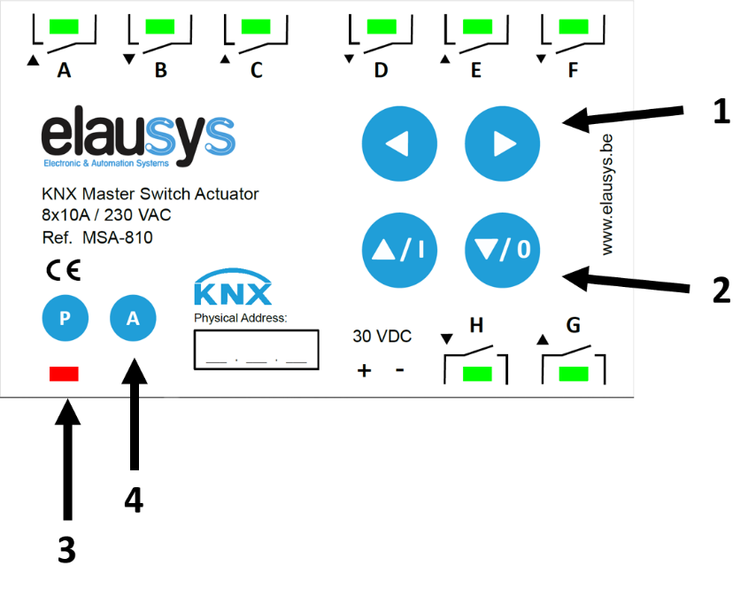
The first two buttons on the top (1) are used to select a channel. When a channel is selected for manual operation, its LED blinks for 30s then returns to the current state of the channel. Each press on a button will move the selection to the next channel. When the last channel of a module is reached, an additional press will move the selection to the first channel of the next configured extension module. To quickly move the selection from one module to another, you can press the button longer (> 0,5s), after each long press, the selection moves to the first channel of the next module. The same applies to the previous channel using the left button, a short press will move the selection to the previous channel while a longer press will move the selection the previous module.
In case a channel is configured for shutter/blind operation using ETS, both channels (Up / Down) and blinking together.
Depending on the selected function, the channel can be turned ON/OFF manually (switching mode) or moved Up/Down (shutter/blind mode) using the two buttons below (2). For shutter/blind channels, a long press on one of these buttons will move the shutter/blind to the upper/lower position while a short press will stop an active channel or perform a step move in the upper/lower direction.
💡 When no application is loading in ETS (or if the KNX was not connected) all channels are set to switching mode by default. Therefore, it is be possible to turn ON any channel manually. Make sure NOT to turn ON both channels of a shutter/blind simultaneously!
The button “P” (3) is the KNX programming mode button. A red light is ON when the programming mode is active.
The button “A” (4) is the addressing mode button for the extension modules. All channels of the master device are blinking while the addressing mode is active. Extensions modules must be addressed once by the master before they can be used in the system. See “Addressing” chapter for the complete procedure.
On this page
Need additional help?
Our support team is available to answer your technical questions.
Contact support