
Connection arrangement
The KNX bus is connected on the top side of the gateway.
An external power supply 12-30VDC is required and connected on the bottom side of the module, beside the RJ45 connector for the ethernet cable.
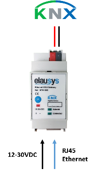
KNX at the top; auxiliary supply and Ethernet at the bottom.
| Front panel element | Meaning |
|---|---|
| Network LED | Physical Ethernet connection is established. |
| Connected LED | Communication with the inverter is established. |
| P button | KNX programming mode. |
| Red LED | KNX programming status. |
Compatibility and limitations
This gateway is intended to be used with a GOODWE inverter compatible with the modbus interface definition. Please refer to the inverter provider to check if your model is compatible with modbus TCP or contact us.