
Skip to content
Elausys

KNX Gateways for Inverters / INV-KNX Kostal User Manual

Hardware and compatibility

Connection diagrams, front-panel indicators and compatibility limits for INV-KNX Kostal.

elausys · 11 September 2026
On this page

Connection arrangement

The KNX bus is connected on the top side of the gateway.

An external power supply 12-30VDC is required and connected on the bottom side of the module, beside the RJ45 connector for the ethernet cable.
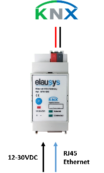
inv-knx-connections.png

KNX at the top; auxiliary supply and Ethernet at the bottom.

Front panel elementMeaning
Network LEDPhysical Ethernet connection is established.
Connected LEDCommunication with the inverter is established.
P buttonKNX programming mode.
Red LEDKNX programming status.

Compatibility and limitations

This gateway is intended to be used with a Kostal inverter compatible with the SunSpec modbus interface definition. The inverter is connected to the ethernet network on the same router as the KNX gateway.

Manual navigation

All chapters of the INV-KNX Kostal user manual

Frequently Asked Questions

Where are the gateway connections?

The KNX bus connection is at the top. The auxiliary 12–30 VDC supply and RJ45 Ethernet connection are at the bottom.

What is the difference between the Network and Connected LEDs?

Network indicates a physical Ethernet connection. Connected indicates communication with the inverter.

What interface must the Kostal inverter support?

The inverter must support the SunSpec Modbus interface and connect to the same Ethernet network/router as the KNX gateway.

Keep exploring

Find the other guides for this product in the documentation.

Back to INV-KNX Kostal User Manual