
Connection arrangement
The KNX bus is connected on the top side of the gateway.
An external power supply 12-30VDC is required and connected on the bottom side of the module, beside the RJ45 connector for the ethernet cable.
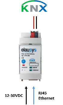
KNX at the top; auxiliary supply and Ethernet at the bottom.
| Front panel element | Meaning |
|---|---|
| Network LED | Physical Ethernet connection is established. |
| Connected LED | Communication with the inverter is established. |
| P button | KNX programming mode. |
| Red LED | KNX programming status. |
Compatibility and limitations
This gateway is intended to be used with a SolarEdge inverter compatible with the SunSpec modbus interface definition. The inverter is connected to the ethernet network on the same router as the KNX gateway.
All SolarEdge inverters with SetApp configuration are SunSpec-supported.
SolarEdge inverters with the LCD that have Firmware version 3.xxxx and above only are SunSpec-supported.