
Connection arrangement
The KNX bus is connected on the top side of the gateway.
An external power supply 12–30 VDC is required and connected on the bottom side of the module, beside the RJ45 connector for the Ethernet cable.
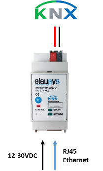
KNX at the top; auxiliary supply and Ethernet at the bottom.
| Front panel element | Meaning |
|---|---|
| Network LED | Physical Ethernet connection is established. |
| Connected LED | Communication with the inverter is established. |
| P button | KNX programming mode. |
| Red LED | KNX programming status. |
Compatibility and limitations
This gateway is intended to be used with a Sigenergy inverter that supports the Modbus TCP interface. Please refer to the inverter provider to check if your model is compatible, or contact us.
Compatible models:
The SigenStor EC, Sigen Hybrid SP/TP and Sigen PV Max share the same Modbus register map and are all supported by this gateway.
Connection:
The inverter is connected to the same local network as the KNX gateway and acts as a Modbus TCP server on port 502.
Limitations:
- The Daily Energy Yield object reports the daily energy exported to grid (it does not include self-consumption or battery charging).
- AC apparent power (VA) is not available on Sigenergy inverters.
- AC voltage and current totals are not available; only per-phase values are provided.
- DC current and voltage totals are not available; only per-PV-string values are provided.