JA-121T communication
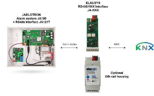
Equip the Jablotron 100 system with a JA-121T RS485 module. Set it to 9600 baud (default) and connect it as shown in Hardware and compatibility. Supply the JA-121T output and JA-KNX from the alarm panel or an external 12 VDC supply. No additional RS485 termination resistor is required.
Exit service mode
RS485 and the KNX interface are disabled when a user is logged in service mode. Exit service mode before testing the gateway.
Prepare the user code
Use a valid alarm user code for area control. The User code field supports the format 1*1234 and a code length of 4 to 6 digits. Four-digit codes without a prefix are supported. See ETS parameter reference.
Prepare PG and area functions
Configure PG events in the Jablotron system as required by the project. The gateway supports PG status and control, zone status, area control and area status. Match the zone offset and area mapping to the alarm system.