Virtual devices
A virtual device has no physical link at all — the server itself holds its state. Virtual devices are the glue of advanced installations. Typical uses:
- Points driven by Node-RED flows (below).
- Device groups — a group is a virtual widget that drives its members (see “Device Groups”).
- Materialized Logic outputs — a function's output turned into a real widget (see “Function Setup & Outputs”).
- Flags and setpoints for automations ("Vacation mode", "Target temperature offset").
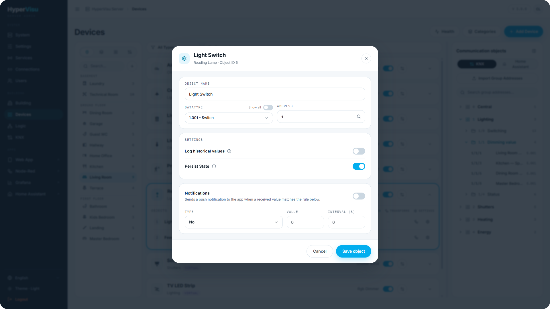
Create them in the Devices workspace like any other widget, with Protocol set to VIRTUAL. Per object you set:
| Setting | Meaning |
|---|---|
| Range - Min / Range - Max | The values the object accepts. A value written from outside (a flow, the webhook) that falls outside the range is refused; a new object starts with 0 to 100. |
| Persist State | Whether the current value survives a server restart. Enable it for flags and setpoints; leave it off for momentary signals. |
A virtual object has no default-value setting. Switch on Persist State if the last value must come back after a restart. The Object ID shown under the title of the object dialog is what a flow or the webhook uses to address the object.
Node-RED
Node-RED is an optional service on the server (enable it in “Services & Protocols”) for building custom flows — MQTT bridges, odd cloud APIs, bespoke logic that does not fit the Logic engine, or a driver for a device HyperVisu does not support.
- Switching it on: on Services, switch on Node-RED. The row shows Changes need a restart; click Restart Server in the Pending Changes banner and wait for the server to come back.
- Opening it: once the service runs, Node-Red appears in the APPS group of the admin sidebar. Click it to open the flow editor in a new tab.
- Connection: Login using your HyperVisu account.
- Driving devices: the Hypervisu nodes of the palette read and write HyperVisu devices directly (see “The HyperVisu nodes” below). Virtual devices are the natural meeting point: the flow computes, the virtual device displays the result and takes part in scenarios, automations and views like any other device.
- Webhook API: flows (and third-party systems) can also use the device webhook API, protected by serial-number verification (see “Webhooks & Third-Party APIs”). The Webhooks switch of the Services page must be on for it (see “Services & Protocols”). Treat the serial number as a secret: anyone who has it can write through the webhook.
💡 Tip: Prefer the Logic engine (see “Logic Engine — Concepts & Canvas”) for standard building logic — it is monitored, validated and visible to residents. Use Node-RED for what only code can do.
The HyperVisu nodes
The Node-RED of the server carries a Hypervisu palette category: one node per device type, plus an Input Target node, two global-command nodes and a Scenario node. A device node stands for one HyperVisu device. Send it a message and the device is commanded; when the device changes, the node sends the new value out of one of its outputs.
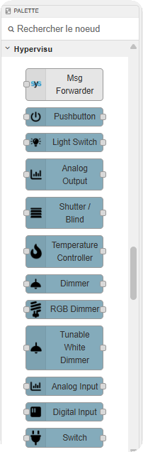
| Node | Device type (see “Widget Types Overview”) | Inputs → outputs |
|---|---|---|
| Pushbutton | Push button | Any message → 1 output |
| Light Switch, Switch | Light switch, Switch | 2 targets → 2 outputs |
| Analog Output | Analog output | A number → 1 output |
| Shutter / Blind | Shutter / Blind | 8 targets → 8 outputs |
| Temperature Controller | Temperature / Thermostat | 5 targets → 5 outputs |
| Dimmer | Dimmer | 4 targets → 4 outputs |
| RGB Dimmer | RGB dimmer | 4 targets → 4 outputs |
| Tunable White Dimmer | Tunable-white dimmer | 6 targets → 6 outputs |
| Analog Input | Analog input | A number → 1 output |
| Digital Input | Digital input | true / false → 1 output |
| Text Input | Text input | A text → 1 output |
| Alarm | Alarm | 7 targets → 7 outputs |
| Audio | Audio | 13 targets → 13 outputs |
| Ventilation | Ventilation | 10 targets → 10 outputs |
| Air Conditioning | Air conditioning | 11 targets → 11 outputs |
| Door Lock | Door lock | 2 targets → 2 outputs |
| Meter | Meter | 4 targets → 4 outputs |
| Charger | EV charger | 8 targets → 8 outputs |
| Global Lights, Global Shutters | Every light or shutter of a room or a category | On / Off, Up / Down — no output |
| Scenario | A scenario | Any message runs it — no output |
| Input Target | — | Adds the target name to a message (see “The Input Target node”) |
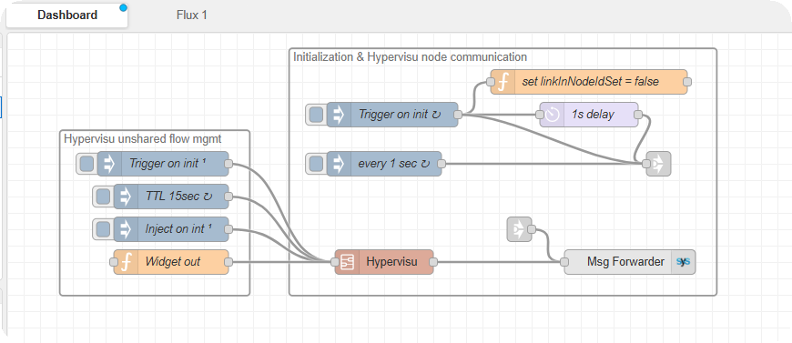
How the nodes reach the server. The Node-RED of the server comes with a Hypervisu subflow already placed in a flow tab, next to the nodes that route messages to and from the device nodes (a link node, a Widget out node and a forwarder node). The subflow signs in to the server with a dedicated service account, loads the rooms, categories, devices and scenarios, and keeps the live connection open. Leave these nodes in place: without them, the device nodes have empty lists and stay silent. The palette also lists a Msg Forwarder node: it is part of this routing, already placed — do not add another one to your flows.
⚠️ Warning: Flows act with full rights, and a Global Lights or Global Shutters node acts on every matching device of the room or category, physical ones included.
Adding a device node
What you need: the Node-RED service on (see “Node-RED” above), an activated server, and the device created in the Devices workspace.
- In the Node-RED editor, drag the node of the device type from the Hypervisu palette category onto the flow.
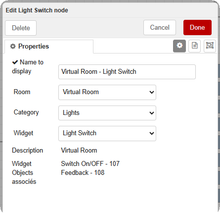
- Double-click the node. The dialog lists the rooms, categories and devices of the installation.
- Choose the Room, then the Category, then the Widget (the device). Each list narrows the next one. The device must be of the node's type: a Dimmer node lists dimmers only.
- Check the Description and the list of objects under it: they show the device's objects with their Object IDs, so you can be sure you picked the right device.
- Name to display fills itself as "Room - Device". Change it if you want another label on the canvas.
- Click Done.
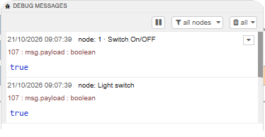
- Wire an inject node (or any node that produces a value) to the input, and a debug node to each output you want to watch.
- Click Deploy.
If a device you just created is missing from the lists, restart the flows (Deploy menu → Restart Flows), reload the editor page and open the dialog again.
Messages in and out
A message to a device node carries two properties:
| Property | Content |
|---|---|
msg.inputTarget | Which object of the device the value is for, by its name — for example Switch On/OFF or Dimming setpoint. The names per node are in “Node reference” below. Use an Input Target node to set it (see “The Input Target node”). |
msg.payload | The value: true / false, a number, a text, or an RGB object {"red": 255, "green": 120, "blue": 0}. |
A message that leaves an output carries the value in msg.payload and the object's Object ID in msg.topic. Output n belongs to target n of the node's list, in the same order.
The targets of a node are of two kinds:
- Commands (Switch On/OFF, Dimming setpoint, Up/Down output…) — sending one commands the device, exactly like a tap in the app.
- Feedback (Feedback, Status feedback, Actual setpoint, Temperature…) — the state the device reports. Writing one from a flow updates the value HyperVisu shows; nothing is sent to the device.
When the outputs fire:
| Output of a… | Fires when |
|---|---|
| Command target | the flow sends that target (the value leaves at once); the app, a scenario, an automation or another flow commands the device — only when the value changes. |
| Feedback target | the device reports a value — every time, even when it repeats. |
ℹ️ Note: The names are case-sensitive. A message with an unknown name, or with no
msg.inputTargeton a node that needs one, is ignored without an error — for exampleSwitch ON/OFFinstead ofSwitch On/OFF.
Node-RED as a device driver
Node-RED can stand in for a device HyperVisu has no protocol for:
- Create a virtual device of the right type (see “Virtual devices” above).
- Add its node to a flow. Wire the command outputs to the nodes that talk to the real device (HTTP, MQTT, serial…).
- Wire the real device's answers back into the node, through an Input Target node set to the matching feedback target.
The residents use the device in the apps as usual; the flow carries the commands out and the state back.
The Input Target node
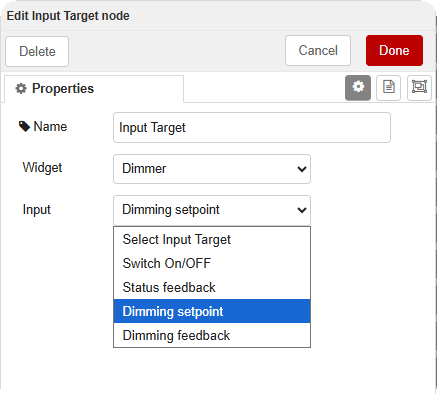
The Input Target node sets msg.inputTarget for you, from a list, so you do not have to type the names.
- Drag an Input Target node between the source of the value and the device node.
- Double-click it.
- In Widget, choose the device type (Dimmer, Shutter/Blind, Audio…).
- In Input, choose the target. The list shows the targets of that type, in the order of the device node's outputs.
- Optionally fill Name. Without one, the node shows the target name on the canvas.
- Click Done, then Deploy.
The node passes every message on with msg.inputTarget added and shows the last value under itself: a green dot with Value: …, or a red ring with No input target selected when Input is empty. One device node usually has several Input Target nodes in front of it, one per target you use.
💡 Tip: In a function node, set the same property yourself —
msg.inputTarget = "Dimming setpoint"; msg.payload = 40; return msg;. A function can then send several targets in sequence withnode.send().
Node reference
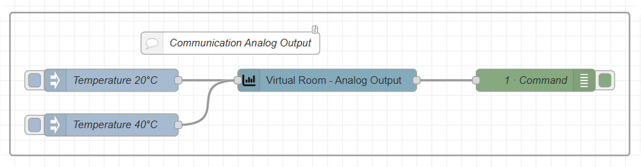
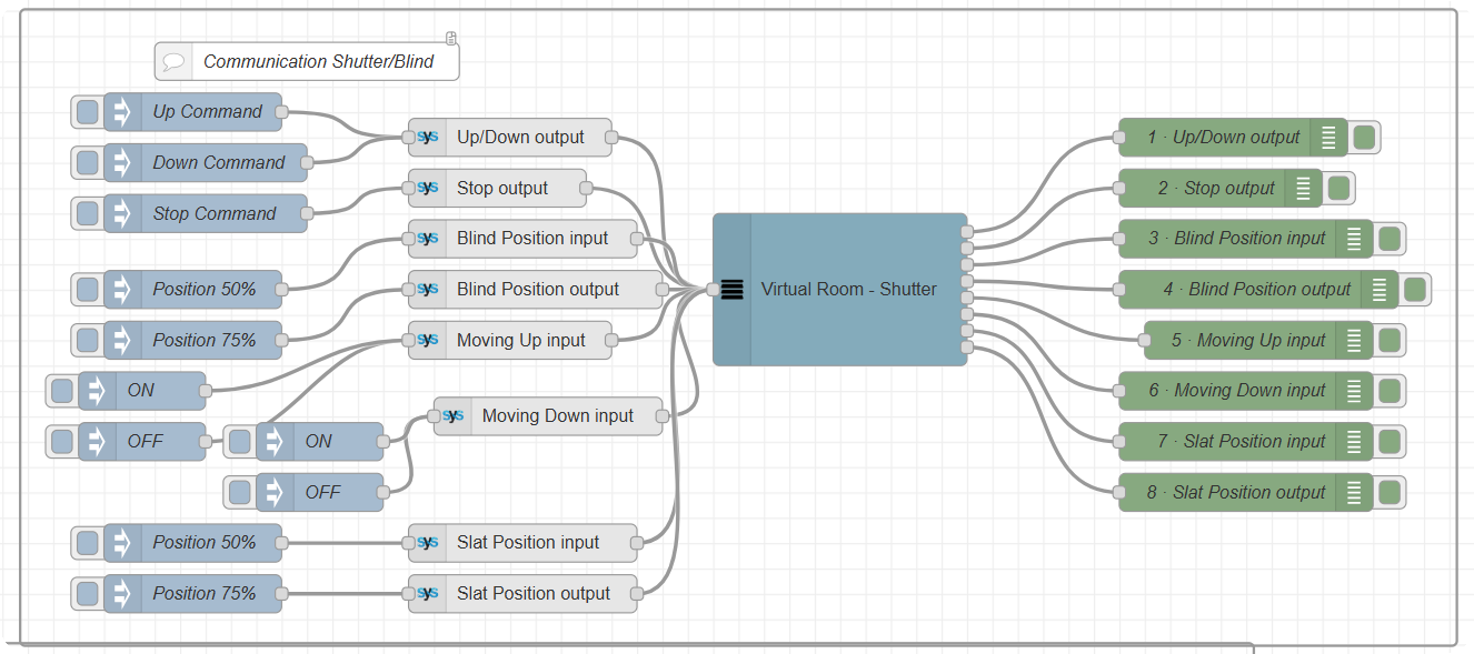
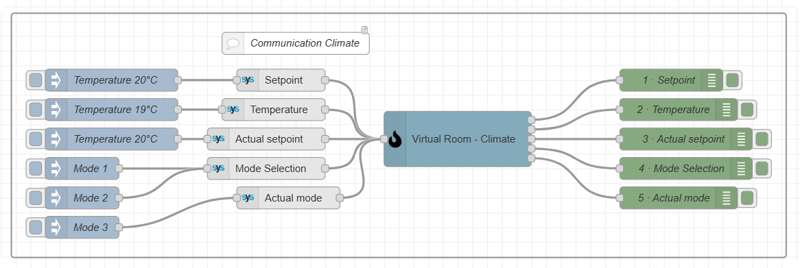
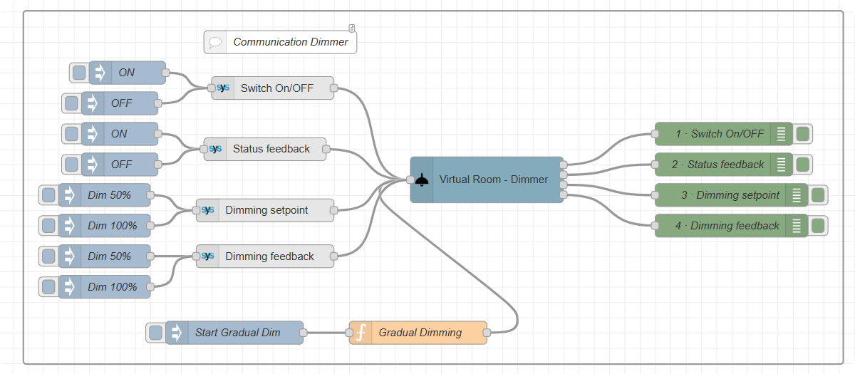
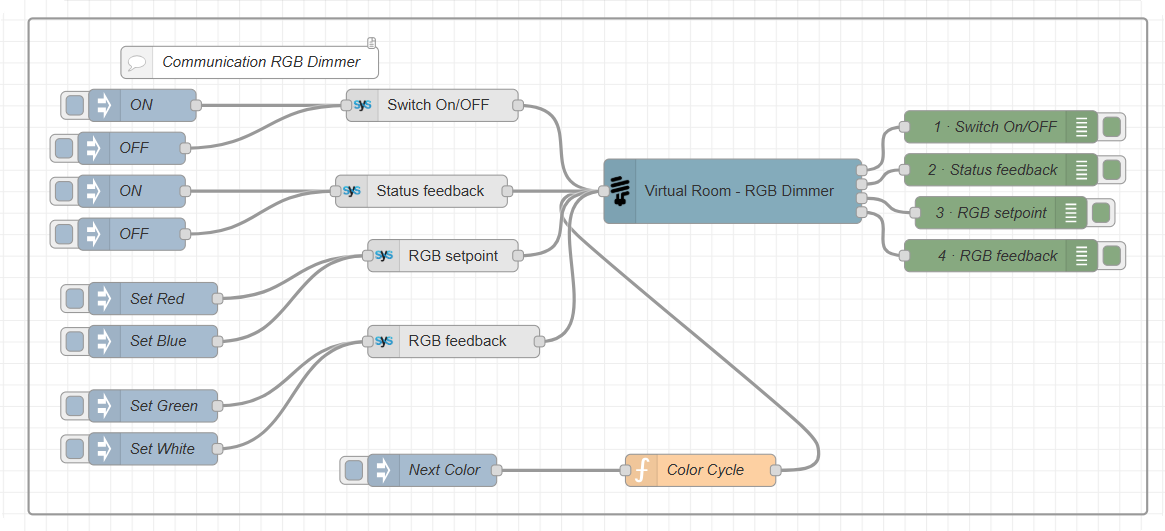
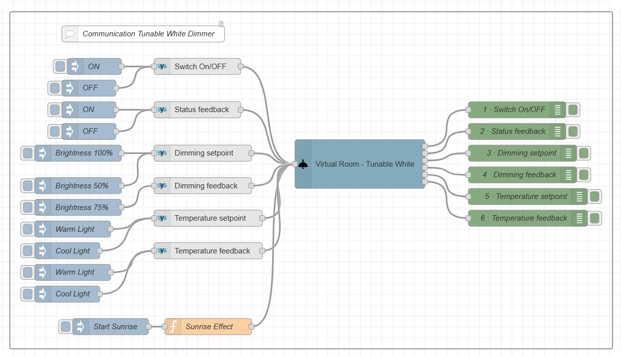
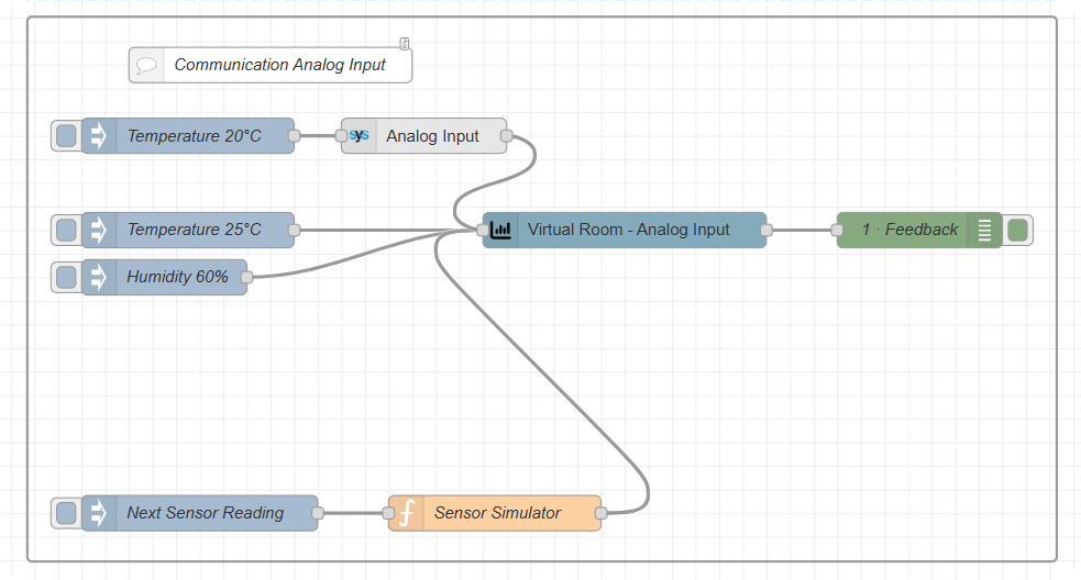
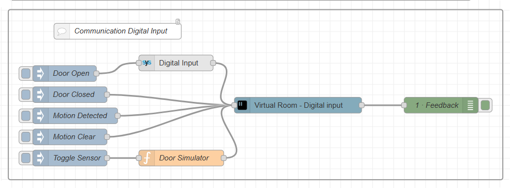
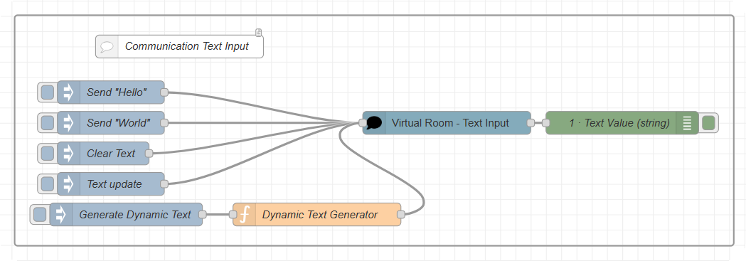
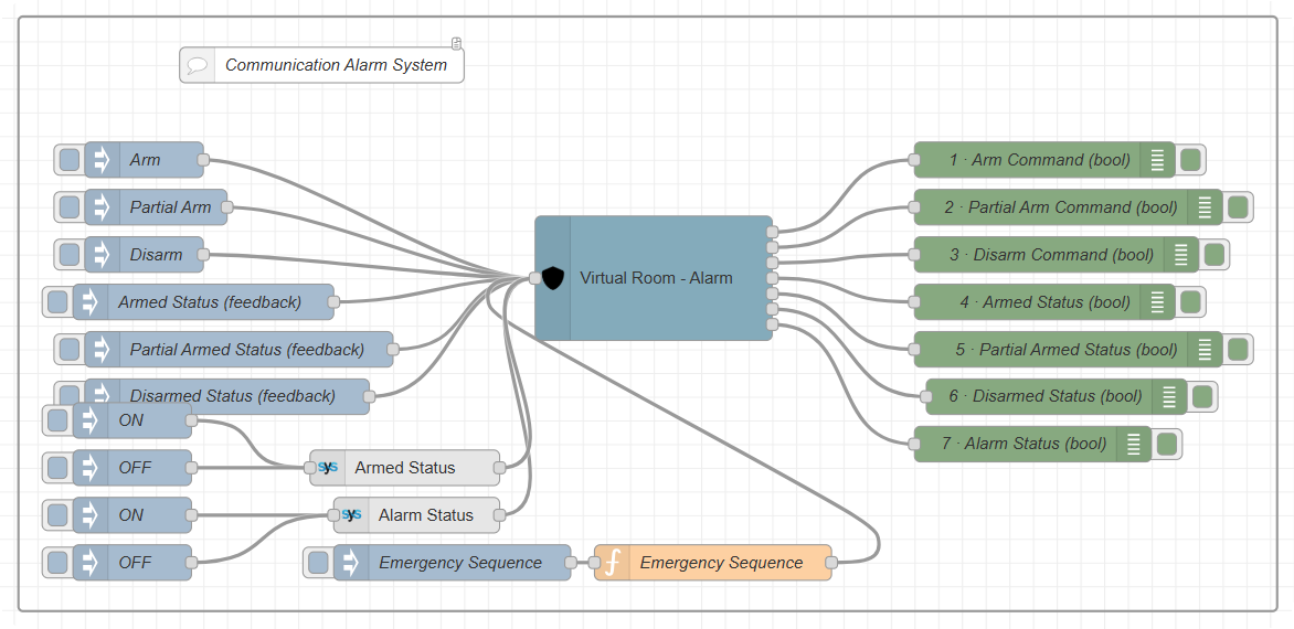
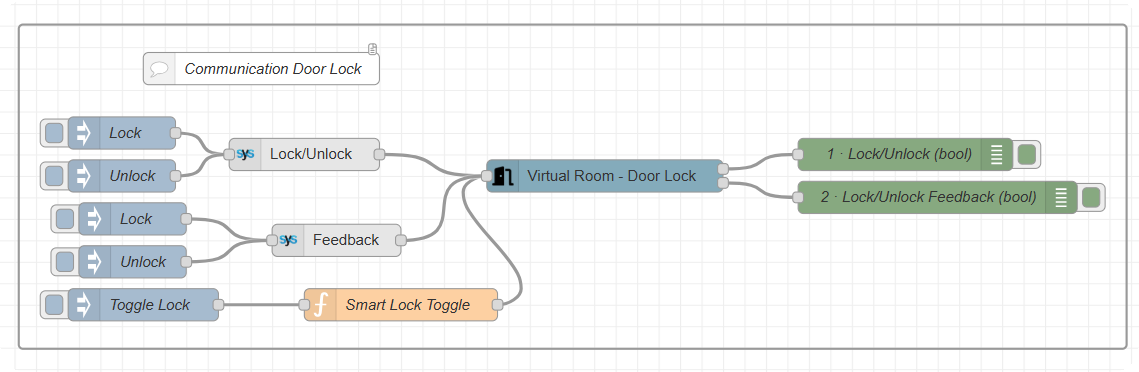
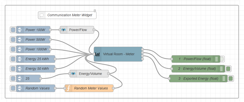
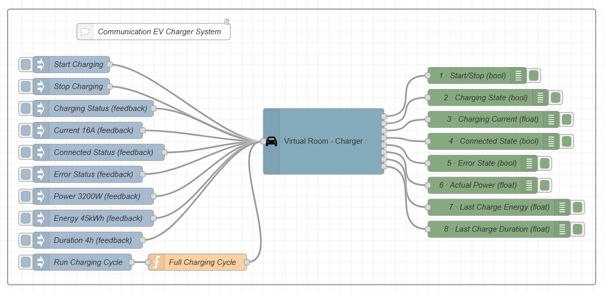
Each entry lists the targets in output order. C = command, F = feedback. The examples come from a test flow on virtual devices: inject nodes on the left, Input Target nodes in the middle, the device node, and one debug node per output on the right.
Importing an example
Every example below comes as a file you can import into your own Node-RED. The device nodes in these files are not bound to any device: they show "(set device)" in their name.
- Download the example file.
- In the Node-RED editor, open the main menu (☰) and choose Import.
- Click select a file to import and choose the file, or paste its content into the dialog.
- Choose current flow or new flow, click Import, then click on the canvas to place the group.
- Double-click the device node and choose the Room, Category and Widget of your installation (see “Adding a device node”). For Global Lights and Global Shutters, choose a room or a category; for Scenario, a scenario. Click Done.
- Click Deploy.
⚠️ Warning: The inject nodes of an example command the device as soon as you click them. Bind the examples to a test or virtual device first, and set the device before you deploy — a device node without a device does nothing but log errors.
Pushbutton
| Input | Output |
|---|---|
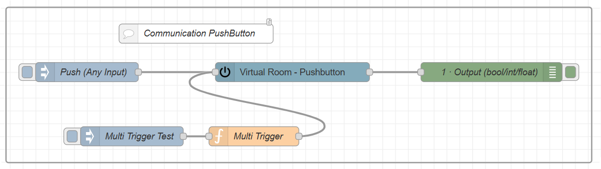
Any message — msg.inputTarget and msg.payload are not needed | 1 · the value sent, each time the button is used (app, scenario or flow), once the server has it |
The device's sub-type decides the value: ON sends true, OFF sends false, Toggle sends the opposite of the last value.
Light Switch and Switch
| # | Target | Kind | Value |
|---|---|---|---|
| 1 | Switch On/OFF | C | true / false |
| 2 | Feedback | F | true / false |
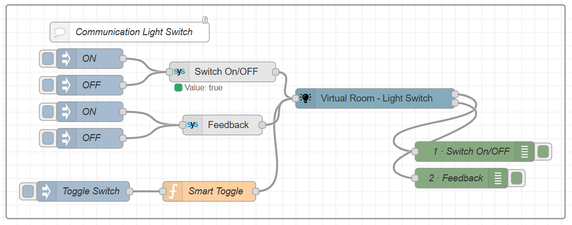
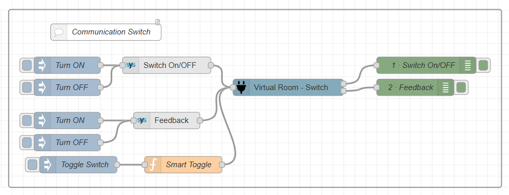
Analog Output
| Input | Output |
|---|---|
A number in msg.payload, within the device's range; msg.inputTarget is optional (Analog Output) | 1 · Command — the value, each time the device is commanded (app, scenario, automation or flow) |
Shutter / Blind
| # | Target | Kind | Value |
|---|---|---|---|
| 1 | Up/Down output | C | false = up, true = down |
| 2 | Stop output | C | true = stop |
| 3 | Blind Position input | F | position 0–100 % |
| 4 | Blind Position output | C | position 0–100 % |
| 5 | Moving Up input | F | true while moving up |
| 6 | Moving Down input | F | true while moving down |
| 7 | Slat Position input | F | slat angle 0–100 % |
| 8 | Slat Position output | C | slat angle 0–100 % |
Positions follow HyperVisu's rule: 100 % is fully closed. Slat targets exist on shutters with slats only. Outputs 1 and 2 fire on every command, even when the value repeats.
Temperature Controller
| # | Target | Kind | Value |
|---|---|---|---|
| 1 | Setpoint | C | °C |
| 2 | Temperature | F | measured temperature, °C |
| 3 | Actual setpoint | F | °C |
| 4 | Mode Selection | C | mode number: 1 Comfort, 2 Standby, 3 Night |
| 5 | Actual mode | F | mode number |
Dimmer
| # | Target | Kind | Value |
|---|---|---|---|
| 1 | Switch On/OFF | C | true / false |
| 2 | Status feedback | F | true / false |
| 3 | Dimming setpoint | C | 0–100 % |
| 4 | Dimming feedback | F | 0–100 % |
RGB Dimmer
| # | Target | Kind | Value |
|---|---|---|---|
| 1 | Switch On/OFF | C | true / false |
| 2 | Status feedback | F | true / false |
| 3 | RGB setpoint | C | {"red": 0–255, "green": 0–255, "blue": 0–255} |
| 4 | RGB feedback | F | same format |
Tunable White Dimmer
| # | Target | Kind | Value |
|---|---|---|---|
| 1 | Switch On/OFF | C | true / false |
| 2 | Status feedback | F | true / false |
| 3 | Dimming setpoint | C | brightness 0–100 % |
| 4 | Dimming feedback | F | brightness |
| 5 | Temperature setpoint | C | color temperature, in the range of the device object |
| 6 | Temperature feedback | F | color temperature |
Analog Input and Digital Input
| Node | Input | Output |
|---|---|---|
| Analog Input | A number in msg.payload, within the device's range; msg.inputTarget optional (Analog Input) | 1 · the value, each time the device reports one |
| Digital Input | true / false; msg.inputTarget optional (Digital Input) | 1 · the state, each time the device reports one |
These are measurements: a value written by a flow leaves the output only once the server has stored it, not at the moment the flow sends it.
Text Input
| Input | Output |
|---|---|
A text in msg.payload; msg.inputTarget optional (Text) | 1 · the text, each time it changes on the server |
The node accepts texts from a flow for a VIRTUAL text device only. On KNX, a text (DPT 16) holds 14 characters at most.
Alarm
| # | Target | Kind | Value |
|---|---|---|---|
| 1 | Arm Command | C | always sends true, whatever the payload |
| 2 | Partial Arm Command | C | always sends true |
| 3 | Disarm Command | C | always sends true |
| 4 | Armed Status | F | true / false |
| 5 | Partial Armed Status | F | true / false |
| 6 | Disarmed Status | F | true / false |
| 7 | Alarm Status | F | true when the alarm is triggered |
No PIN is asked, even when the alarm is protected by one.
Audio
| # | Target | Kind | Value |
|---|---|---|---|
| 1 | Volume setpoint | C | 0–100 |
| 2 | Volume feedback | F | 0–100 |
| 3 | Zone On/Off | C | true / false |
| 4 | Zone feedback | F | true / false |
| 5 | Mute On/Off | C | true / false |
| 6 | Mute feedback | F | true / false |
| 7 | Play/Stop | C | true = play, false = stop |
| 8 | Play/Stop feedback | F | true / false |
| 9 | Source selection | C | source number |
| 10 | Source feedback | F | source number |
| 11 | Previous/Next | C | false = previous, true = next |
| 12 | Track Title | F | text |
| 13 | Track Artist | F | text |
Output 11 fires on every press, even when the value repeats.
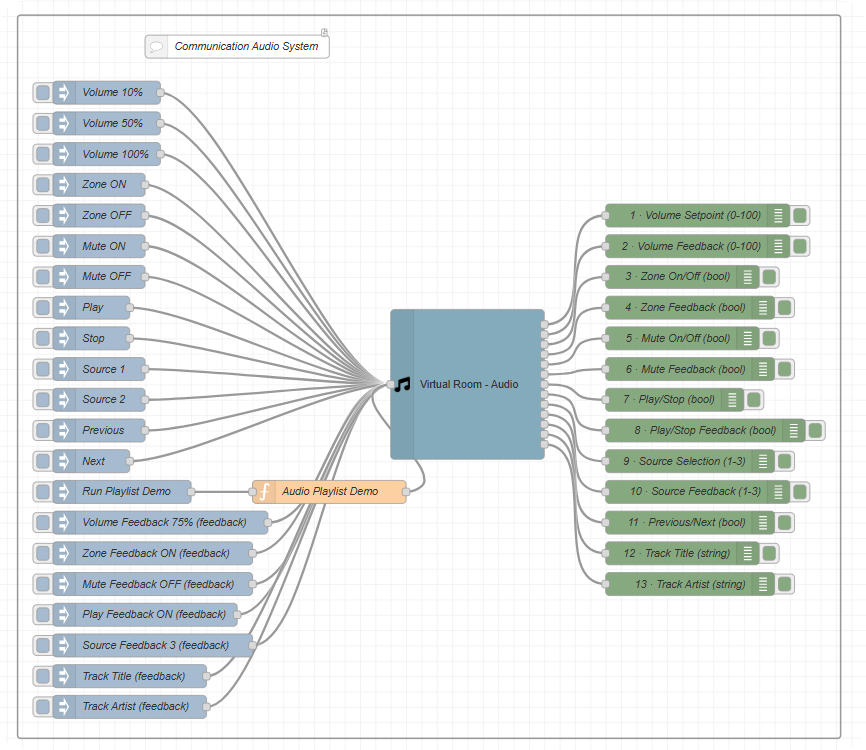
Ventilation
| # | Target | Kind | Value |
|---|---|---|---|
| 1 | Auto On/Off | C | true / false |
| 2 | Auto feedback | F | true / false |
| 3 | Slow On/Off | C | true / false |
| 4 | Slow feedback | F | true / false |
| 5 | Medium On/Off | C | true / false |
| 6 | Medium feedback | F | true / false |
| 7 | High On/Off | C | true / false |
| 8 | High feedback | F | true / false |
| 9 | Boost | C | true / false |
| 10 | Boost feedback | F | true / false |
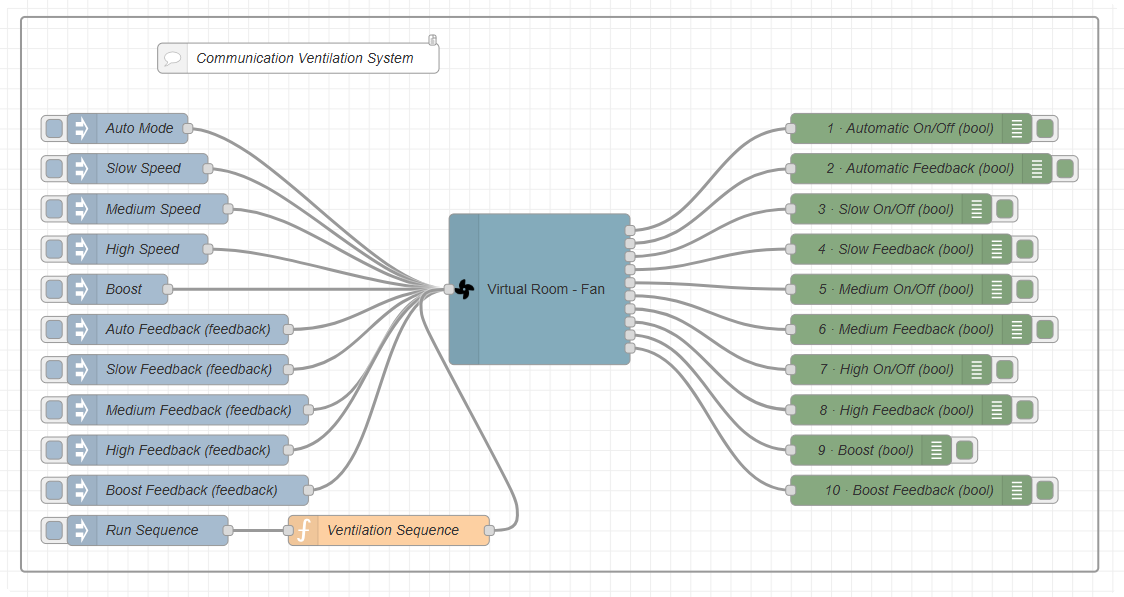
Air Conditioning
| # | Target | Kind | Value |
|---|---|---|---|
| 1 | On/Off | C | true / false |
| 2 | On/Off feedback | F | true / false |
| 3 | Heating Mode | C | true |
| 4 | Heating feedback | F | true / false |
| 5 | Cooling Mode | C | true |
| 6 | Cooling feedback | F | true / false |
| 7 | Auto Mode | C | true |
| 8 | Auto feedback | F | true / false |
| 9 | Setpoint | C | °C |
| 10 | Actual setpoint | F | °C |
| 11 | Temperature | F | measured temperature, °C |
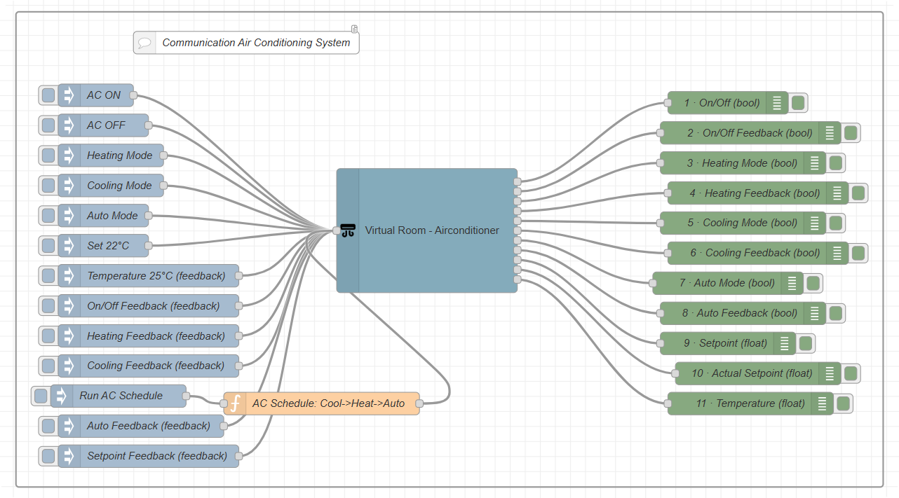
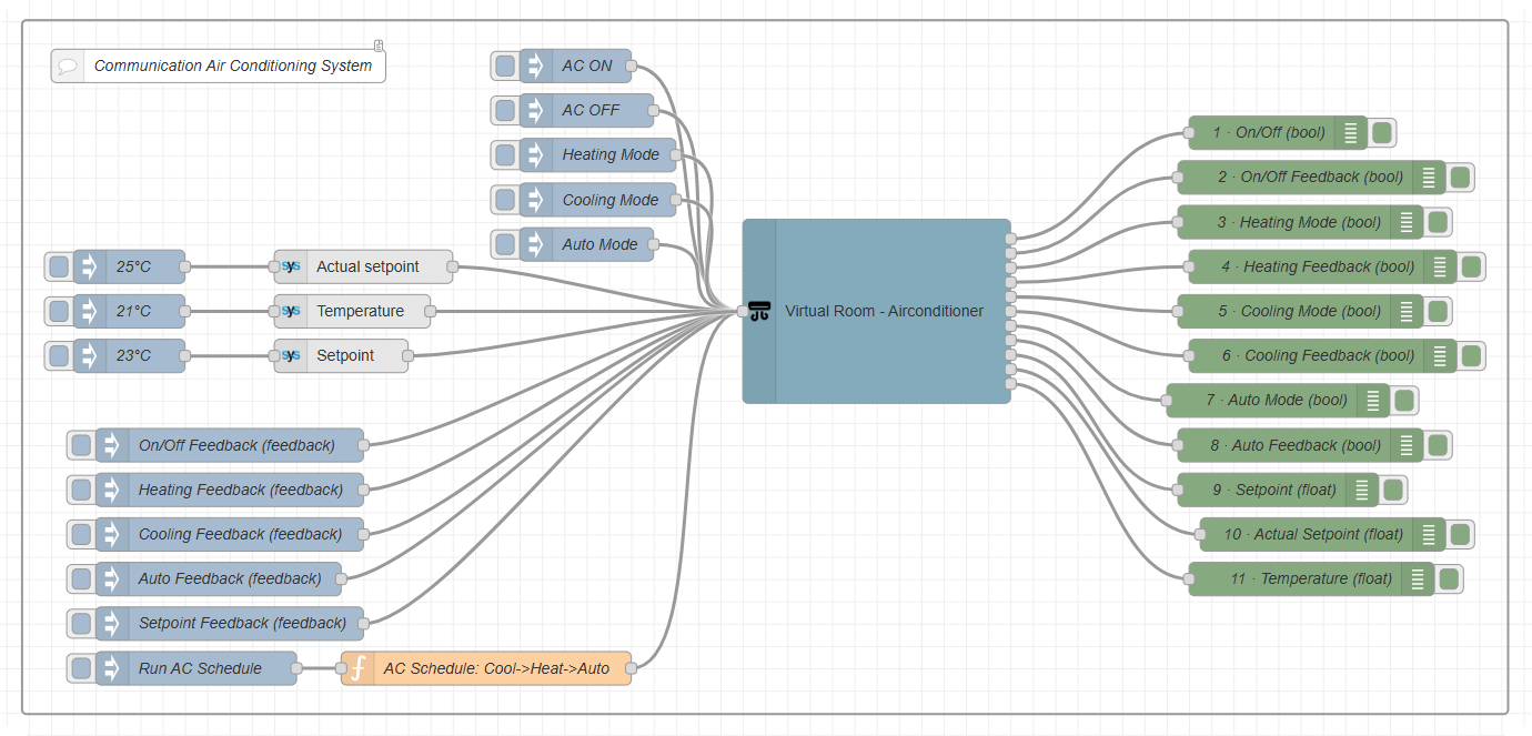
Door Lock
| # | Target | Kind | Value |
|---|---|---|---|
| 1 | Lock/Unlock | C | true = lock, false = unlock |
| 2 | Feedback | F | true / false |
Meter
| # | Target | Kind | Value |
|---|---|---|---|
| 1 | Power/Flow | F | number (W, or a flow for water and gas) |
| 2 | Energy/Volume | F | number (kWh, or a volume) |
| 3 | Exported Energy | F | number (kWh) |
| 4 | State Of Charge | F | number (%) |
Without msg.inputTarget, the value goes to Power/Flow. A meter only has the objects of its role (see “Widget Types Overview”): a grid meter has no state of charge. A value written by a flow leaves the output once the server has stored it.
Charger
| # | Target | Kind | Value |
|---|---|---|---|
| 1 | Start/Stop | C | true = start, false = stop |
| 2 | Charging | F | true / false |
| 3 | Charging Current | C | A |
| 4 | Connected | F | true when a vehicle is plugged in |
| 5 | Error | F | true / false |
| 6 | Actual Power | F | W |
| 7 | Last Energy | F | kWh of the last session |
| 8 | Last duration | F | duration of the last session |
Global Lights, Global Shutters and Scenario
| Node | In the dialog | Input | Output |
|---|---|---|---|
| Global Lights | Room or Category (choosing one clears the other) | msg.inputTarget = On or Off; the payload is ignored | — |
| Global Shutters | Room or Category | msg.inputTarget = Up or Down | — |
| Scenario | Scenario | Any message runs the scenario | — |
The global nodes send the same command as the app's global buttons: every light, or every shutter, of the room or category.
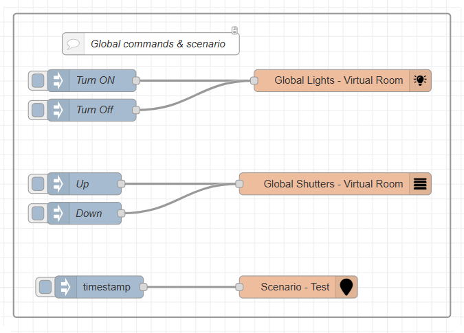
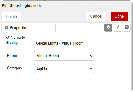
ℹ️ Note: When you reopen a Global Lights or Global Shutters node, both lists show a value — the Category list simply shows its first entry. The node acts on the list you changed last: here the room, as its name says. To switch to a category, choose it in Category (the room is then cleared).